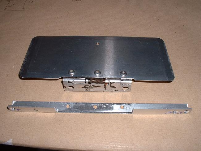

So a new, smaller glove-box door is made, with an angle-piece to support it. I will be making a new shallower glovebox in which we can put a chart, spare batteries, toothbrush, condoms etc, and other essential touring supplies.
Instrument Panel
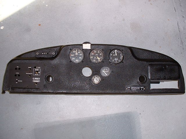
| Instrument panel. I had previously removed the old paint and hammered out some dents and generally tarted it up a bit. | ||
|
|
We wanted a transponder in the right hand
glove-box for touring in Europe, where many countries now make transponder mandatory. The
transponder was installed in 2001 for a tour of Germany and Austria. So a new, smaller glove-box door is made, with an angle-piece to support it. I will be making a new shallower glovebox in which we can put a chart, spare batteries, toothbrush, condoms etc, and other essential touring supplies. |
| You may note in the
right hand photo above, a small rectangular hole to the left of the transponder... this
was put in some years ago so that we could withdraw the rod that goes through the fuselage
fuel tank. This small rectangular hole means that the whole panel does not need to
be removed to drop the tank. The hole will be covered by a plate with the "fuel transfer" label attached to it. |
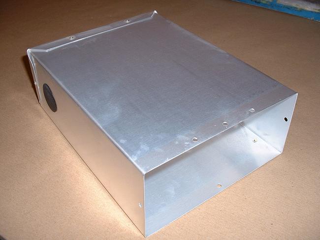 |
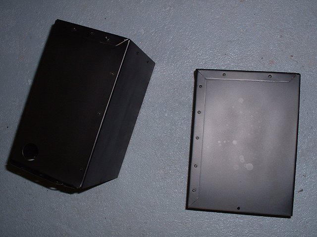
New shallow glove box for the space above the
transponder. Before riveting up, the aluminium has been acid-etched and treated
using Poly-Fiber "Aluma-Dyne", which leaves no colour. Blanked-off hole is for any future electrical / power supply access in case we put a gadget inside the box. Anyone designing a hand-held / portable transponder? |
 |
I make a new left-hand glove box. In this we install two gel-cell batteries, an intercom, PTT connections, GPS power supply and all necessary fuses. One battery will operate the Icom hand-held radio, the other one powers the GPS. If the radio battery gets low, a throw-over switch changes the radio source to the GPS battery and vice-versa. The GPS is quite happy to continue to draw power from the battery that the radio was draining, because the GPS has a lower power requirement. |
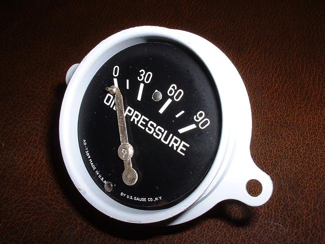 |
The instruments are given the once-over...in this case the oil pressure gauge has been stripped and the corroded case cleaned up and epoxy-primed before reassembly. I still need to repaint the needle, and I will be marking the limits on the gauge face instead of on the glass as was previously the case... |
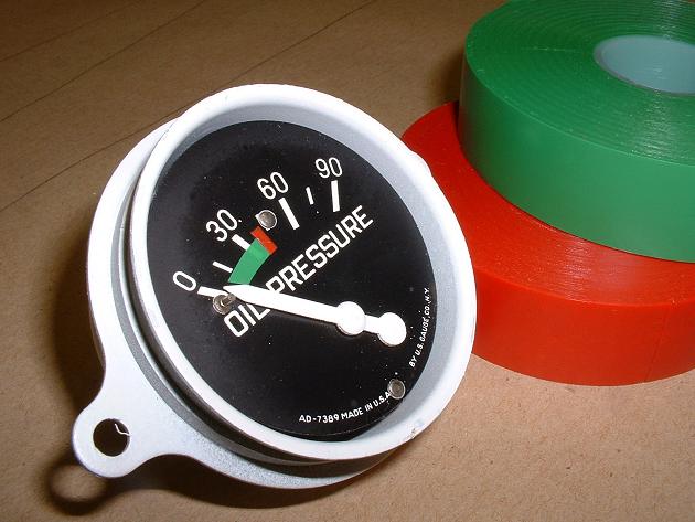 |
...and here it is marked up with the limits and a painted needle. I used regular electrician's insulating tape for the markings, referencing the type cert and Service Manual to ensure I put the correct limits in. |
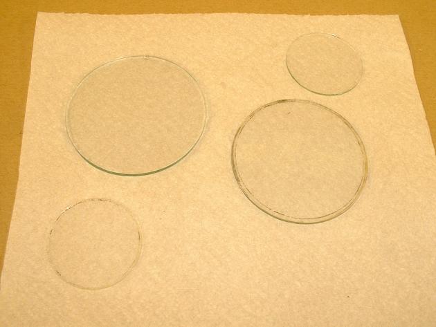 |
The instrument glass faces getting prepared for a clean up. |
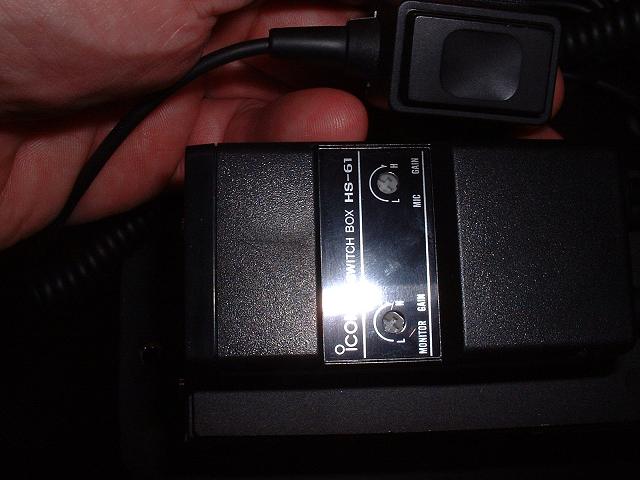
We operate an Icom IC-A20 Handheld, connected through a Flightcom intercom, all powered by 12 volt gel-cells. There is no secret about hooking up the Icom IC-A20 with an intercom...but you need from Icom the "magic box" that contains the necessary electronic wizardry, it is called a Switch Box HS-61. It comes complete with a PTT on the end of a long coiled cable for attachment to the yoke, and the intercom plugs into it with standard headset plugs (all fitted)...or you could forego the intercom & plug the headset straight into the HS-61. The box has adjustments for mic gain.
An excellent combination, with better range and clarity than most certificated permanent installations. We have 3 Taylorcrafts operating with exactly this installation, all are perfect. |
 |
The rudder bars & brake pedals are gloss-coated white and finished off with some 3M grippy paint, which I acquired from unnamed sources, but some sand mixed in with regular paint would do equally well, I'm sure. |
 |
 |
The panel gets a final clean-up, etch prime and three coats of wrinkle paint (it looks a lot better than this photo). Note transponder slot on the right hand side. Also painted in smooth semi-gloss black are the panel bits, including here the two glove boxes (smaller glove box fits above transponder). |
 |
The panel almost fully fitted out. I dismantled all the instruments and serviced the internals, cleaned the faces and glass and repainted the needles & bezels. Oil temp gauge is also complete, but will not be fitted until the panel is installed. |
 |
 |
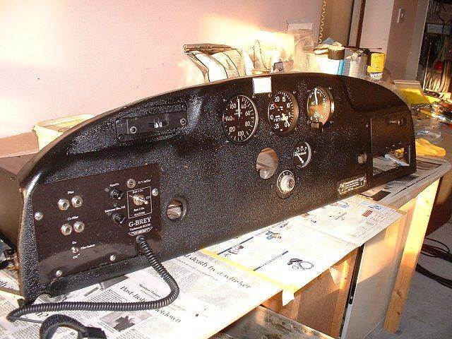
The panel fully fitted out except the temp
gauge & transponder (both to be fitted when I install the panel in the fuselage).
Plate on left hand side hides the two gel cells, intercom & power switches.
Flexible cable is ptt to be attached to the yoke. White rectangle between
airspeed & tacho is the compass correction card. Note the fuel transfer label plate that hides the cut-out for fuselage tank rod removal. Further description here. |
 |
The panel goes in for a trial fit of the boot cowl, coaming and windscreen. Much fettling required, I fear. |
 |
The windscreen needs some minor re-drilling of the mounting holes. |