My Taylorcraft
restoration project, G-BREY
Page 2, January - June 2003
Go to page 1 2 3 4 5 6 7 8
by Robert Lees
Click on the thumbnails to
enlarge, use the browser's Back button to go back.
January 2003 Click on the thumbnails to enlarge, use the
browser's Back button to go back.
 |
 |
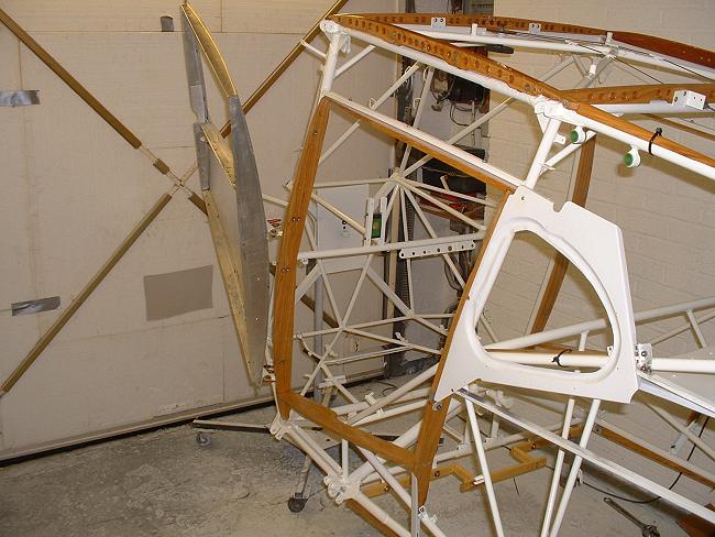
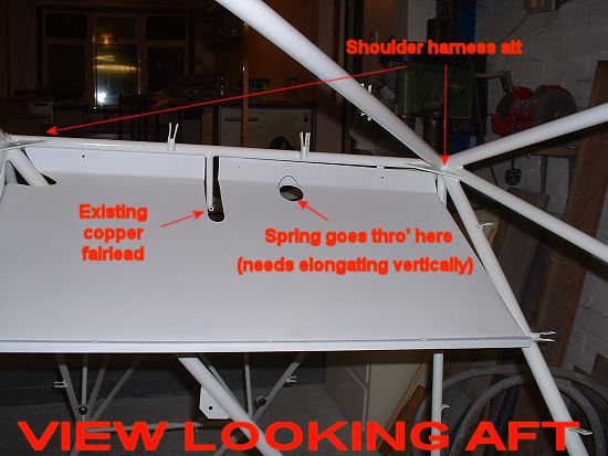
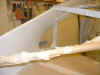
Views showing two different dummy rigs for aft
trim pulley, so as to set up the correct operating system of the trim. The first
shows the fuselage uncovered; the second a modification to permit the dummy pulley to be
installed after covering..... |
 |
 |
...and here's the new forward pulley, in the
process of setting up the trim indicator. Much maintenance work was done over the
decades in the past to get this operating correctly...perhaps one of CG's mistakes
was to have an overly-complicated indicator.
Both fore and aft pulleys are new, manufactured from 5mm thick Tufnel.
[Right-hand photo shows new spindle also made March 2004: Thanks, David.] |
 |
 |
 |
Bead blasting those smaller components.
Parts which need to be identified for location were stamped upon removal so that I know
where to fit them back! |
 |
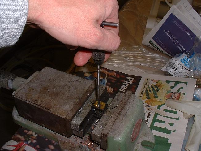
All the woodwork in, now. Here I'm
tapping out the varnish residue from the threaded inserts that will hold the skylight
down. |
 |
 |
More spraying! Note on the fuel tank in
the left picture the reinforcing plates welded in to prevent strain & cracking when
tightening the fittings. |
 |
 |
 |
More permanent reassembly! The varnished
frames, painted D windows, hat shelf. Some of the fairing pieces are held on
temporarily with black cable ties until I fabric them on. |
 |
Hatshelf detail |
Also much fabric work, summarised
here.
February 2003 Click on the thumbnails to enlarge, use the
browser's Back button to go back.
 |
Existing control surface pulleys were serviceable, but
needed re-bushing, since the original bushes had worn loose in the pulleys.
Therefore pulley bore opened out and new phosphor-bronze bushes turned and
press-fitted in. The bush rotates around the bolt, not the pulley rotating around the
bush.
Bush is slightly wider than pulley, so preventing the side of the pulley
interfering with the bracket..
|
 |
 |
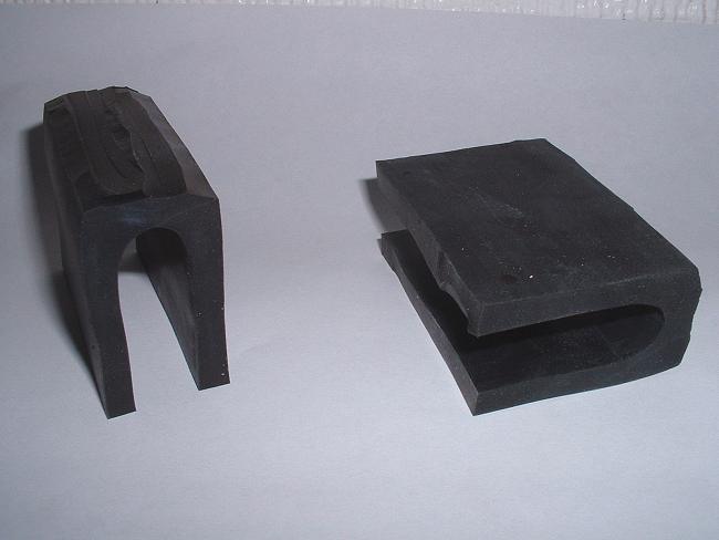
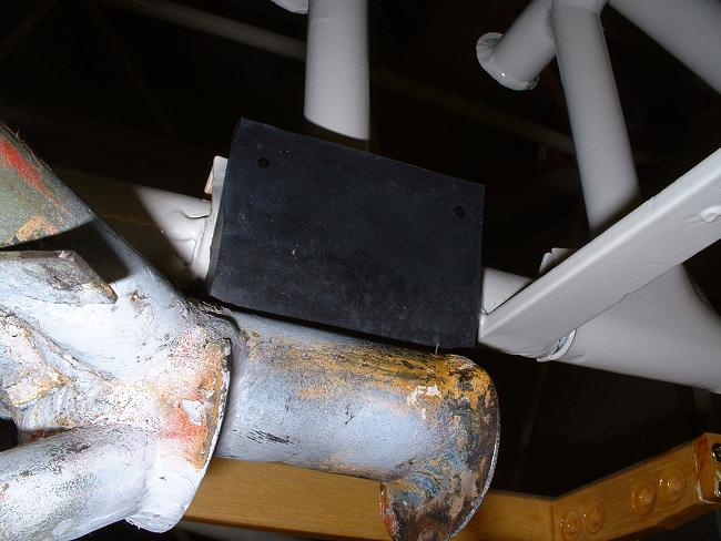
Replacement gear bumpers...supplied courtesy of my local
(3500 miles) hardware supply house, thanks, Jon. Modified in accordance with a
certain sketch in a certain Owner's Club newsletter. |
Late February 2003 Click on the thumbnails to enlarge, use the
browser's Back button to go back.
 |
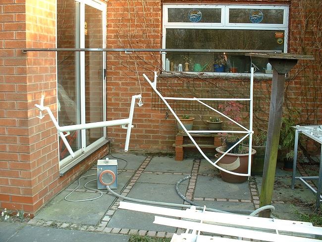
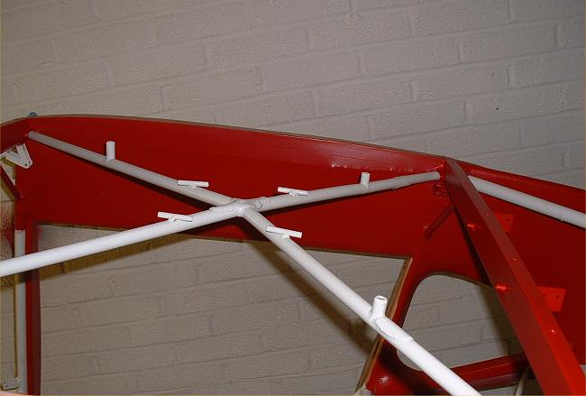
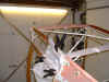
More spraying of components, this time the
control "H" frame and fin. 2-part acrylic used. Note the blue HVLP
spray machine, used for all the spraying...cheap, portable and efficient. Car air
filters (orange colour) used to clean the intake air. I decided after this photo
that I should protect the patio and brickwork from overspray! |
 |
Andy comes round to assist with the set-up and
alignment of the elevators. All tubes and ribs were bent, so after straightening,
the horn bolt holes will be redrilled. |
 |
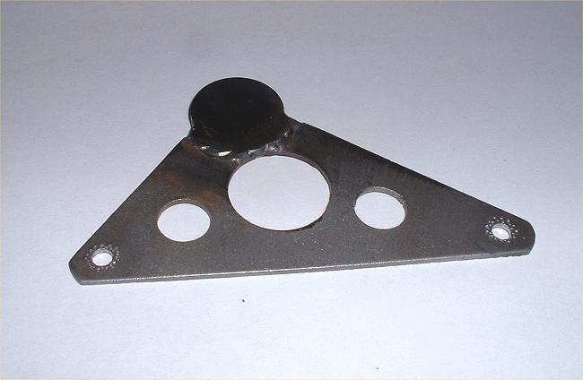
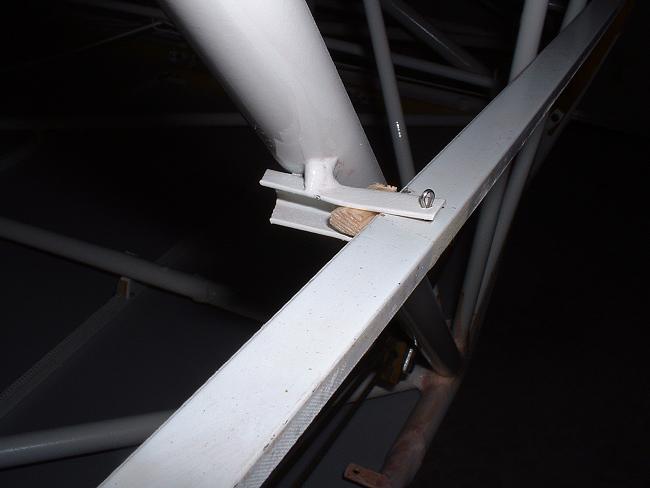
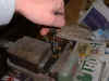
During this process, the trim bellcrank is
reworked (see
elevator trim system in original condition). The two extreme holes have been
punched and then reamed back to correct size (thanks to Forrest for the tip). The
existing central boss containing the pivot hole is constructed using two reinforcing
plates welded either side of the main plate. In mine, punching wouldn't work
because of the small gap between the plates, so I cut the whole thing off and made a
1" diameter 3/16" thick button to weld in. The faces were even precision
ground, but with it to be welded in, this was probably overkill! The photo shows the
as-yet-not-welded button, and the bellcrank sits on a photocopy so that I drill the hole
in the right place! |
 |
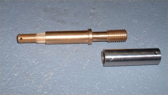
And here it is welded in, I have yet to drill
and ream the 3/16" diameter hole.
Have you seen my new bronze trim screw and stainless barrel (on the right)? Thanks,
David, for your excellent machining skills.
All these changes and new parts and re-sizing of holes (including those on the actuating
arms) gets rid of every ounce of trim tab slop! |
 |
Control column
 |
 |
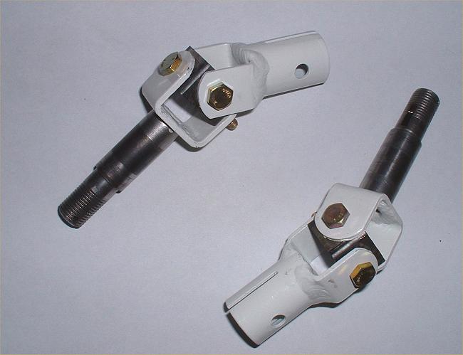
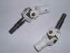
Further control system work also continues on
the universal joint [UJ] of the control column. Much of the "slop" in the
aileron system was caused by very elongated holes in the central part of the UJ system,
much too much to "punch and re-ream" so I welded up the out-of-round holes and
redrilled them. It is important to note that each pair of opposing 3/16" diameter
holes are displaced from each other, this gives clearance between the AN3 bolts that are
at 90 degrees inside this assembly! This far left pic shows a "before and after"
pair. The section is 3/4" internal seamless square. The adjacent pic
shows the 3/16" taper reamer. |
 |
 |
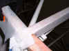
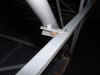
And here they are installed (albeit
temporarily, without the correct castellated nuts & split pins). But no slop!
The spindles have a spiral groove machines into them to assist with distribution of
lubricating oil. CG knew his stuff! There is an oiling hole right on top of
the H frame arms. As the "H" frame swings fore-and-aft, it distributes the
pool of oil towards these helix grooves. |
 |
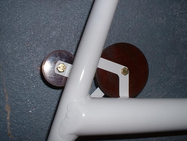
I also had some trouble with the pulleys fitted
to the control "H" frame...they had a tendency to rub against the sides of the
frames that they are bolted to. I didn't know this until I tried to reassemble. This
had evidently been the case for a long time (and perhaps since new) because in order to
rectify the situation, I needed to straighten these frames that hold both the small and
large diameter pulleys. I would suggest that anyone doing a restoration should check
this before final painting!
Fortunately, I was able to get all the pulleys to free-run without damaging the
paintwork too much, with the judicious use of a hammer and some washers.
I would now challenge anyone to have free-er running pulleys than me! (and mine are
bushed, none of this ball-bearing stuff!) |
The feeling of progress being made is
gratifying!
 |
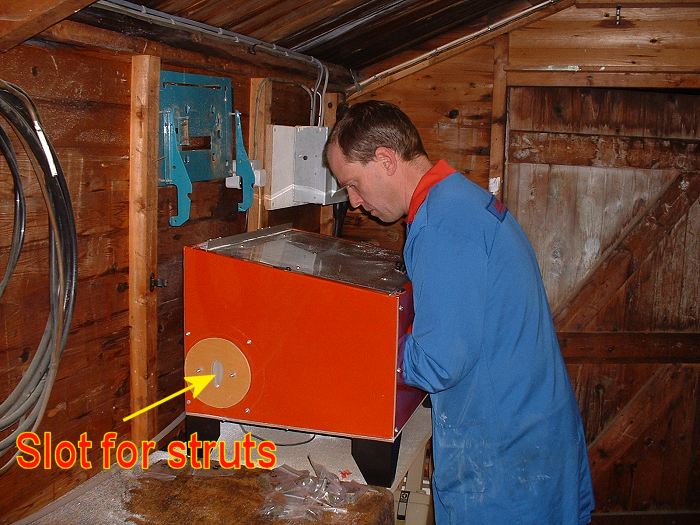
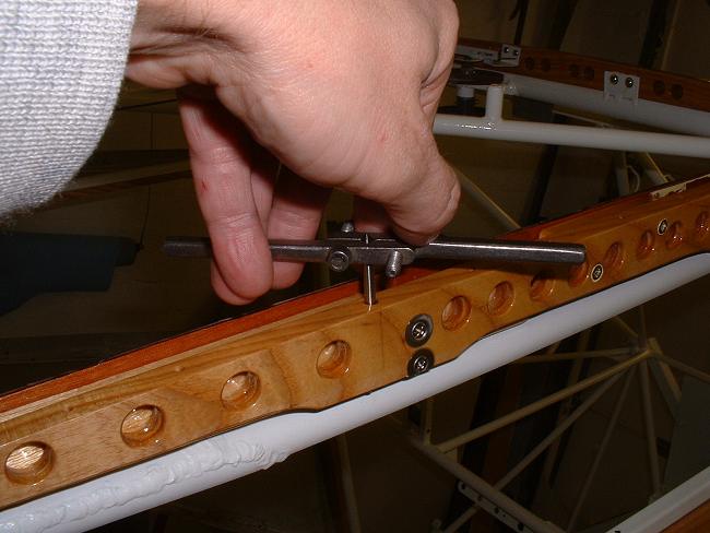
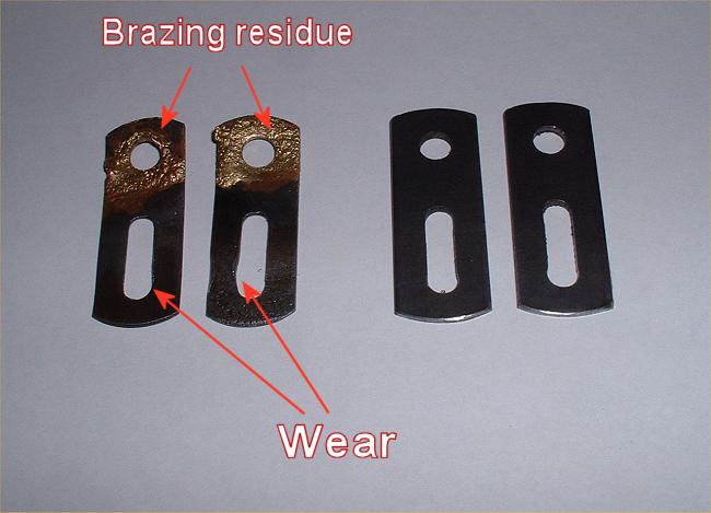
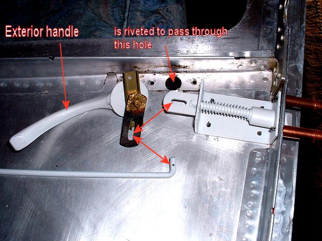
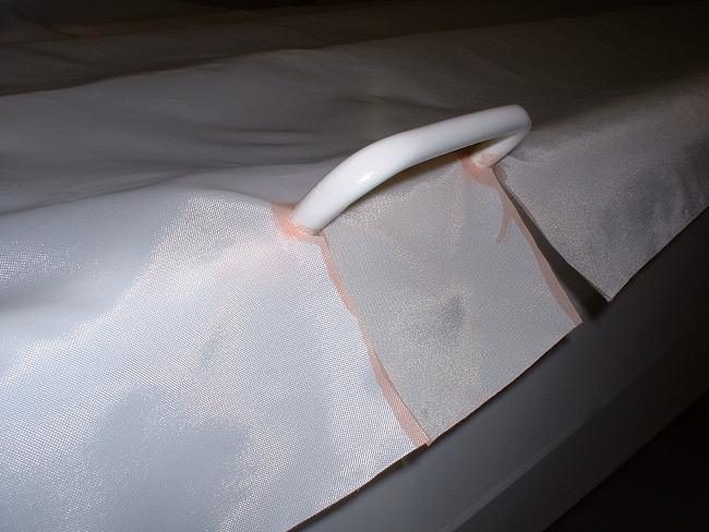
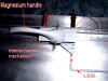
Further to previous
work on the doors, the pic on the left shows two old and two new door opening
tabs. The old ones were worn in the slots, this led to the exterior door handles
rattling. The pic on the right shows where these items fit.
These tabs were originally removed by un-brazing them from the handle spindles to
facilitate removal of the magnesium
handles from the spindles by driving out the pin through the handle. |
 |
 |
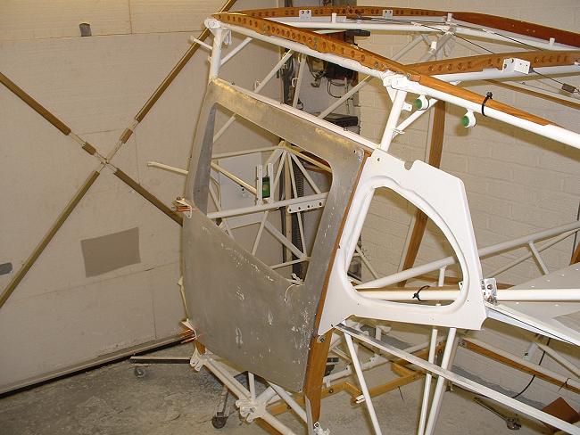
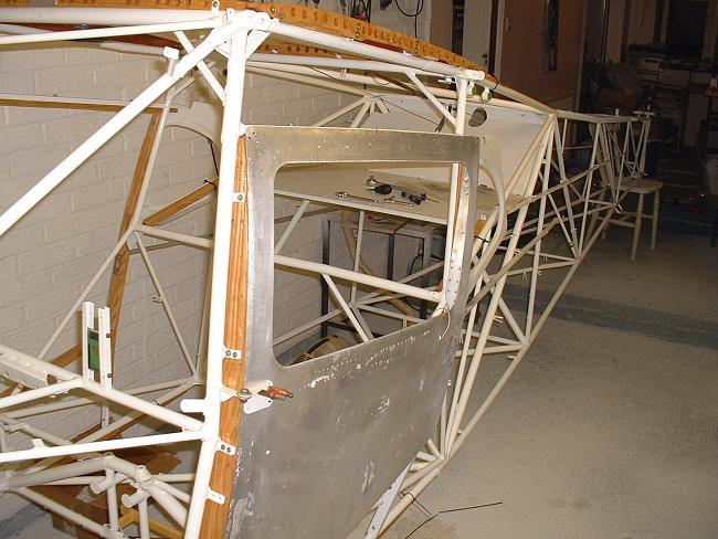
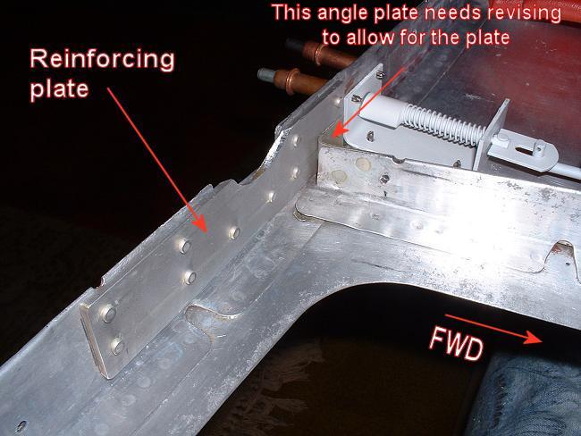
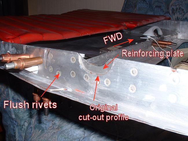
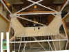
The doors were also reinforced where there is a
semi-circular cut-out for the diagonal tube. There is a tendency for the doors to
flex here, so a good beefy aluminium patch is riveted in to minimise this. Note how
much smaller a cut-out is actually required as compared with the factory original.
Note also the flush rivets used on the outside where the door closes against
the frame. However, some modification required to the interior window frame is
required to avoid the shop head, and a new right-angle piece is fitted to allow for the
locally increased thickness. Note the epoxy primed door handle in the right-hand
photo, this was primed very soon after magna-dyning (see
earlier text). |
 |
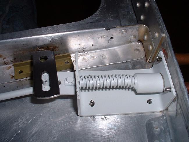
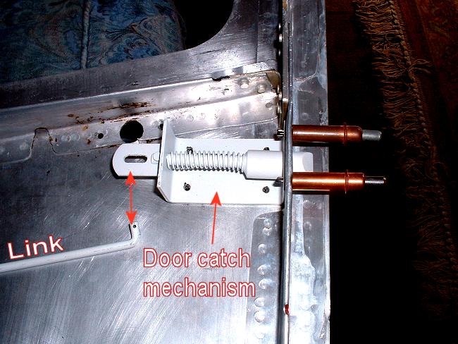
More door mechanism photos:
 |
 |
 |
 |
 |
I am going to have my interior handle pointing
forward to keep out of the occupants' way. |
March 2003 Click on the thumbnails to enlarge, use the
browser's Back button to go back.
 |
 |
 |
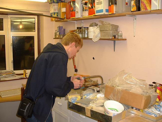
Jon Timlin and his son Jason pay a brief visit
to inspect progress. Jason is conscripted to help make a new fairlead.
Check out Jon's Taylorcraft website. |
 |
More small parts get the white gloss...in this
case the wheels. The same 2-part Acrylic used on the cabin tubes. |
Late March 2003:
Summary of interior cabin fabric: Click on the thumbnails to enlarge, use the
browser's Back button to go back.
 |
 |
 |
 |
 |
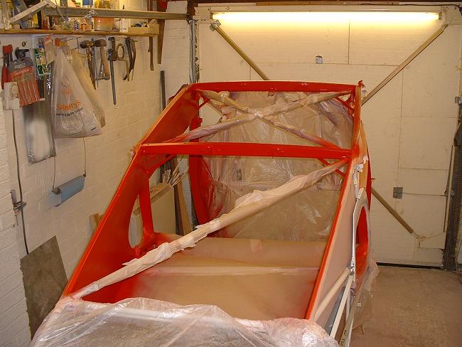
Fabricking of the fuselage interior.
Quite difficult around the D windows and fiddly around the wooden skylight frame. |
 |
Interior fabric during the "pink goo"
stage of the Stits process. |
 |
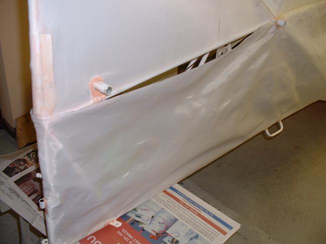
Aluminium frame is glued in, to be covered in
fabric. This frame will allow access to the wing tank fittings from inside the
cabin. Frame is inside the wing root area so that it will not be seen from inside
the cabin. |
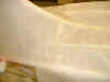
 |
Fabric patch placed on the inside of the wing
root. |
 |
The cabin interior fabric goes silver... |
 |
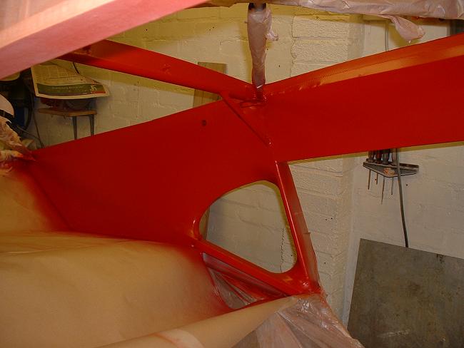
...and a white undercoat is sprayed on the
silver to act as a base for the red topcoat... |
 |
...followed by a mist coat of the red top
coat... |
 |
 |
...and three coats of the final colour, in this
case, Poly-Fiber "Christen Eagle Red". To improve gloss level, a small
amount of high-temperature retarder is used, and all liquids were soaked for 24 hours in a
cold room (my fridge). These measures slow down the solvent evaporation rate, and
improve the gloss level. |
 |
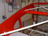 |
After removal of masking, the effect is quite
pleasing. |
April 2003, Fabric work on the fuselage exterior
commences. Click on
the thumbnails to enlarge, use the browser's Back button to go back.
The order for covering the fuselage
is somewhat dictated by the need to join the two sides of the fin to the fabric that lies
on top of the fuselage. I received a lot of help and advice from many folk on this,
but my own choice was dictated by the need to cover the top of the fuselage before the
sides.
This was because, as can be seen from previous photos, I had painted my interior
before covering the exterior, and if I covered the sides first, I would ruin the interior
where I would need to attach the side fabric.
By attaching the top fabric before the sides, I would protect this finish.
Besides, someone I know has an Auster fuselage in the covering stage at the local
airport, and the following sequence is approved by the CAA, so I could use this as a
guide!
|
 |
I decided to do the bottom first
(this had no bearing on the top/sides discussion). This would give me a bit of
practice without the end result being too visible. First thing was to cut a bolt
from the roll to somewhere approximating the shape and size needed. Cheap plastic
clamps help throughout this procedure.
The green label marked "Cable!" (bottom centre) is to remind me to
install the elevator pulleys and elevator & rudder cables prior to closing up the
fuselage. |
 |
The existing aluminium section
stringers were reused (these looked like they were from screen doors). I blocked
each attachment point with wood so that the split pin would not be taking all the fabric
tension loads. |
 |
 |
The fabric was carefully glued around the
extremities, and also the important cut-outs. |
 |
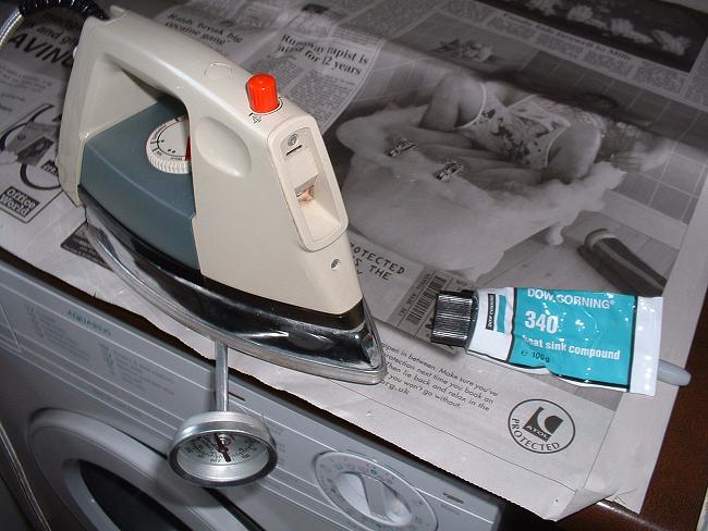
An important step...calibration of
the iron, using heat-sink compound to ensure good contact between the iron plate &
thermometer... |
 |
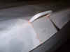
...and then heat taughtening in two
stages in accordance with the Poly-Fiber manual (although a similar process is used in the
Ceconite system). |
 |
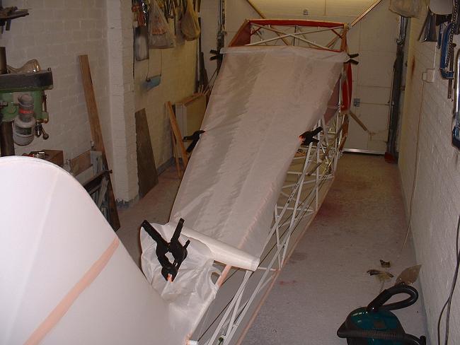
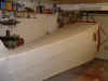
The finished result viewed the
correct way up. The fabric is wrapped a long way around the longerons. This
means that adhesive need not be applied too close to where the fabric departs the longeron
on its way across the width of the fuselage....such gluing can "grab" the fabric
in a dip and spoil the visual appearance. |
 |
 |
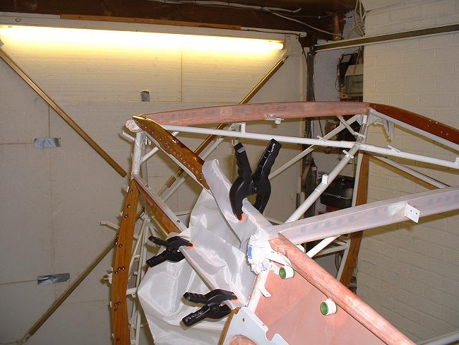
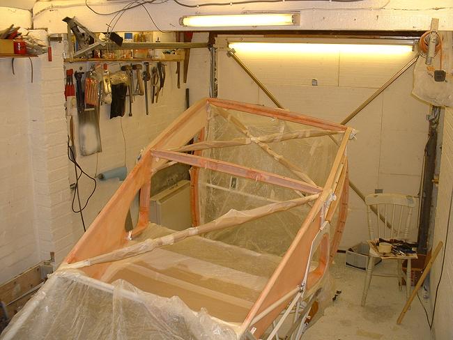
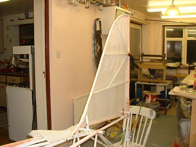
Now for the top. I decided to do the fin
halves separate from the fuselage sides because this was the only way to ensure the top
was complete before the sides. The longitudinal seam at the base of the fin will be
hidden by the horizontal stabiliser. Having smaller pieces to handle was also
useful!
I also made a fin alignment jig, to ensure that the fin remains vertical when
taughtening the fabric.
The "pink goo" stripe is there because I considered stitching before the
final heat taughtening, but this proved unnecessary. |
 |
I heat-taughtened the fin sides to
the first 250 degree stage and then started gluing the top fabric. |
 |
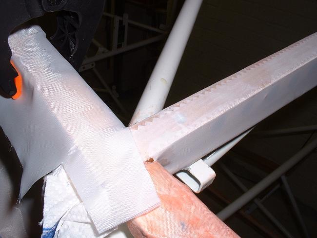
After gluing the top fabric to
within a foot or so of the fin, I marked out where I wanted the 2" glued overlap to
come. This is somewhat guesswork, but is generally dictated by where the minimum
amount of compound curve lies. |
 |
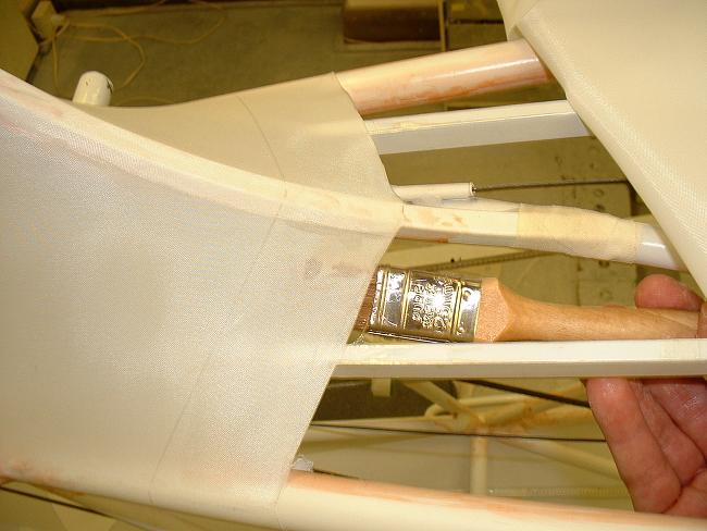
The fin fabric is then trimmed to
size, and a pre-coat of adhesive brushed on to its underside (up to the pencil line) to
aid adhesion. |
 |
I have glued the top fabric to
within a foot or so of the join. The as-yet unshrunk top fabric is lined up with my
fin fabric, and the join line pencilled in. A brush-line of glue over the pencil
line ensures that when cut, the top fabric will not unravel or feather. |
 |
After trimming to my aft pencil
line, the top fabric is glued to the fin fabric, and the last foot of gluing the top
fabric to the upper longerons is finished off. |
 |
The top fabric can now be
heat-shrunk to the first 250 degree stage, after which the fin sides and then the top can
be shrunk to the full 350 degrees. A small amount of low-temperature ironing
smoothed out the last remaining unevenness of the glued joint. |
 |
 |
And here's the end result, a neat 2"
overlap with the top fabric on top of the fin fabric. This join will need to be
taped with a 3" tape for security. The upper fin rib will need stitching too,
where I previously applied a strip of pink goo. |
 |
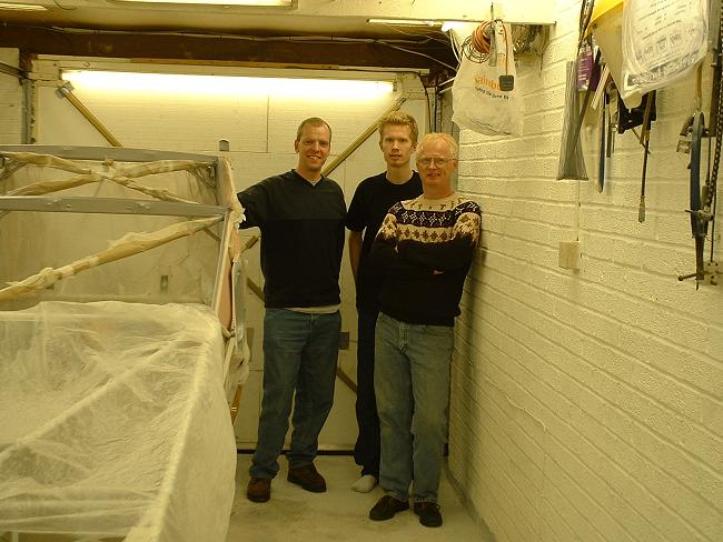
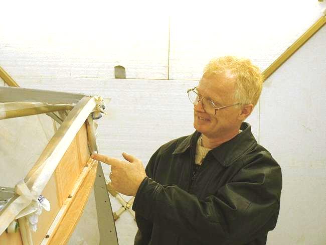
In April, Fred Johnson and Dave Bland take
valuable time out from some top-level ale-drinking to inspect progress. Fred owns
two Taylorcrafts in the States, one of which is undergoing restoration. Both these
chaps were in the UK as part of top-secret global investigations into Taylorcraft and
Pitts construction methods. |
May 2003, Fuselage fabric continues. Click on the thumbnails to enlarge, use the
browser's Back button to go back.
 |
 |
Starboard side fabric laid out and gluing
starts. It can be seen how much slack that can remain during the gluing process.
This slack will all disappear with heat shrinking. |
 |
Those little T-Pins, available from
covering suppliers, are virtually useless straight....so I bent mine (with padded pliers)
to get them through the fabric. They leave quite a large hole, so only insert them
where a covering tape will later go. |
 |
 |
Around protrusions, a seam of
Poly-Brush is applied to prevent the threads unravelling. |
 |
 |
Gluing around the D window and the door
aperture. Note fabric goes under door catch. |
 |
Here's where the side fabric joins
the fin. |
 |
The finished side. Now for my
Inspector to inspect the fuselage interior before closing the fuselage up on the fourth
side. |
Mid May 2003, panel Work. Click on the thumbnails to enlarge, use the
browser's Back button to go back.
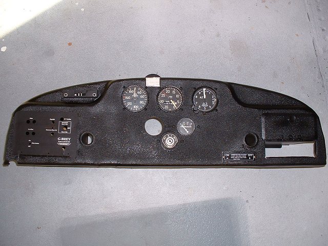
| While I await my Inspector, I
continue with the instrument panel. I had previously removed the old paint and
hammered out some dents and generally tarted it up a bit. |
 |
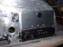 |
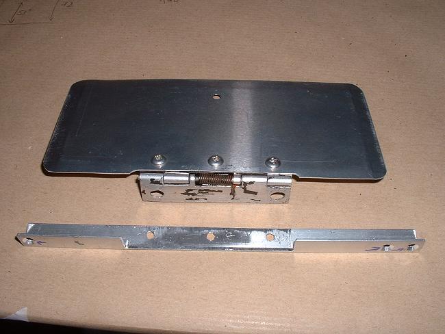
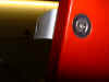
We wanted a transponder in the right hand
glove-box for touring in Europe, where many countries now make transponder mandatory. The
transponder was installed in 2001 for a tour of Germany and Austria.
So a new, smaller glove-box door is made, with an angle-piece to support it.
I will be making a new shallower glovebox in which we can put a chart, spare batteries,
toothbrush, condoms etc, and other essential touring supplies. |
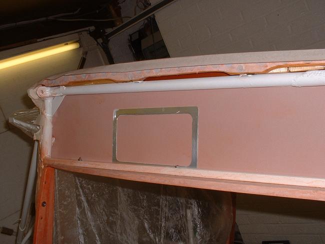
You may note in the
right hand photo above, a small rectangular hole to the left of the transponder... this
was put in some years ago so that we could withdraw the rod that goes through the fuselage
fuel tank. This small rectangular hole means that the whole panel does not need to
be removed to drop the tank.
The hole will be covered by a plate with the "fuel transfer" label
attached to it. |
 |
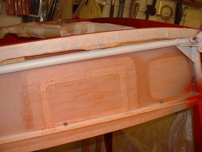
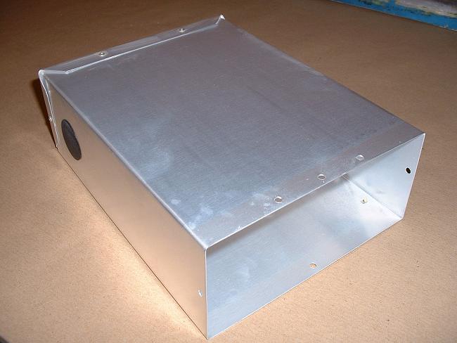
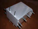
New shallow glove box for the space above the
transponder. Before riveting up, the aluminium has been acid-etched and treated
using Poly-Fiber "Aluma-Dyne", which leaves no colour.
Blanked-off hole is for any future electrical / power supply access in case we put
a gadget inside the box. Anyone designing a hand-held / portable transponder? |
 |
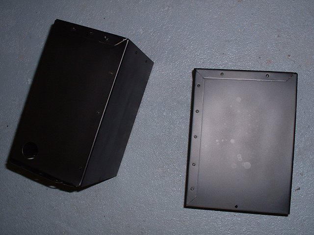
I make a new left-hand glove box. In this
we install two gel-cell batteries, an intercom, PTT connections, GPS power supply and all
necessary fuses. One battery will operate the Icom hand-held radio, the other one
powers the GPS. If the radio battery gets low, a throw-over switch changes the radio
source to the GPS battery and vice-versa. The GPS is quite happy to continue to draw
power from the battery that the radio was draining, because the GPS has a lower power
requirement. |
 |
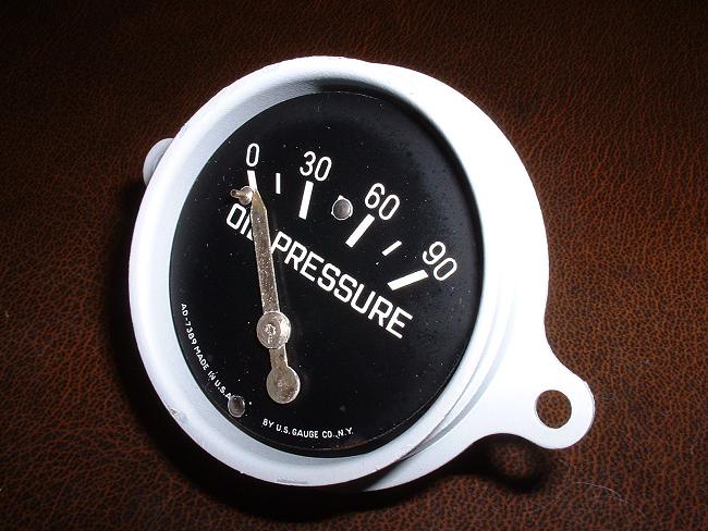
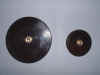
The instruments are given the once-over...in
this case the oil pressure gauge has been stripped and the corroded case cleaned up and
epoxy-primed before reassembly. I still need to repaint the needle, and I will be
marking the limits on the gauge face instead of on the glass as was previously the case... |
 |
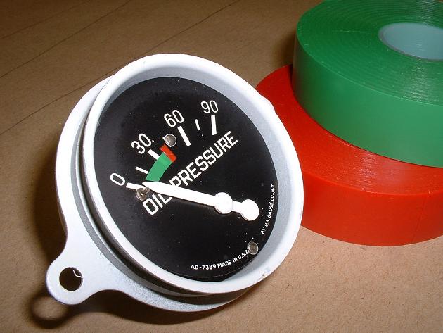
...and here it is marked up with the limits and
a painted needle. I used regular electrician's insulating tape for the markings,
referencing the type cert and Service Manual to ensure I put the correct limits in. |
 |
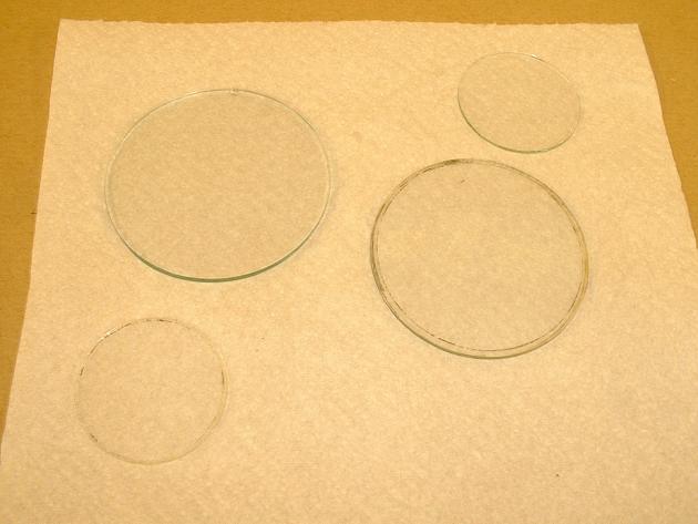
The instrument glass faces getting prepared for
a clean up. |
Other things this month: Click on the thumbnails to enlarge, use the
browser's Back button to go back.
 |
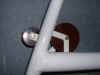
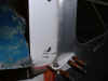
The windscreen attachment brackets get
installed. Because of the new wooden door frames, some minor fettling is required to
get these brackets to align properly. And I was so convinced that I had made the
holes in exactly the same place as the original wood! Here you can see I need to
move the bracket inwards so that the outer face is flush with the outside of the red
doorpost. Note the stainless countersunk washers to spread the load. The
woodwork was rebated to permit these to lie flush, and the washer presses the painted
fabric into the rebate for a neat finish. |
 |
I can now start to see how the windscreen
fairings will need to be modified to align up correctly. I will be making all new
pieces here, because of the aluminium corrosion. |
 |
The pilot's eye view is improving...who needs
instruments, anyway? And I always wanted to be open cockpit, non-radio... |
 |
 |
The whip antenna is serviced...including
removing 1/2 lb of excess cable. It is mounted on the wing root fitting so that the
whole fuselage frame acts as the ground plane, no aluminium sheet required. The whip
sticks up over the wing band fairing. Length of whip is approx 21". I
might put in a proper ground wire due to the paint on the frame. An old ELT whip is
used on one of our other Tcrafts, this works fine. |
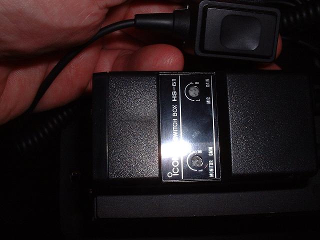
We operate an Icom IC-A20 Handheld, connected through a
Flightcom intercom, all powered by 12 volt gel-cells.
There is no secret about hooking up the Icom IC-A20
with an intercom...but you need from Icom the "magic box" that contains the
necessary electronic wizardry, it is called a Switch Box HS-61. It comes complete with a
PTT on the end of a long coiled cable for attachment to the yoke, and the intercom plugs
into it with standard headset plugs (all fitted)...or you could forego the intercom &
plug the headset straight into the HS-61. The box has adjustments for mic gain.
 
An excellent combination, with better range and clarity than
most certificated permanent installations. We have 3 Taylorcrafts operating with
exactly this installation, all are perfect.
|
 |
The rudder bars & brake pedals are
gloss-coated white and finished off with some 3M grippy paint, which I acquired from
unnamed sources, but some sand mixed in with regular paint would do equally well, I'm
sure. |
Early June spent doing really important things...like a
weekend trip by Taylorcraft & hire car around the Somme battlefields in northern
France, and a long weekend fly-out to the Le Mans 24 hour race. Also my annual
fly-in at our home field, Leicestershire
Aero Club, where I flew the Howard T Minus...a pre-war
Taylorcraft airframe with clip wing and 135 hp engine.
Mid - Late June 2003 Click on the thumbnails to enlarge, use the
browser's Back button to go back.
 |
 |
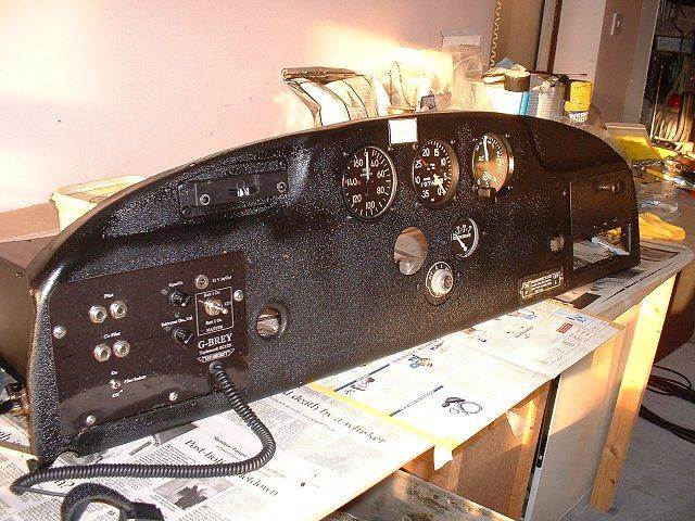
The panel gets a final clean-up, etch prime and
three coats of wrinkle paint (it looks a lot better than this photo). Note
transponder slot on the right hand side. Also painted in smooth semi-gloss black are
the panel bits, including here the two glove boxes (smaller glove box fits above
transponder). |
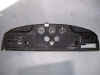 |
The panel almost fully fitted out. I
dismantled all the instruments and serviced the internals, cleaned the faces and glass and
repainted the needles & bezels. Oil temp gauge is also complete, but will not be
fitted until the panel is installed. |
 |
 |
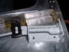
The panel fully fitted out except the temp
gauge & transponder (both to be fitted when I install the panel in the fuselage).
Plate on left hand side hides the two gel cells, intercom & power switches.
Flexible cable is ptt to be attached to the yoke. White rectangle between
airspeed & tacho is the compass correction card.
Note the fuel transfer label plate that hides the cut-out for fuselage tank rod
removal. Further description here. |
 |
The panel goes in for a trial fit of the boot
cowl, coaming and windscreen. Much fettling required, I fear. |
 |
The windscreen needs some minor re-drilling of
the mounting holes. |
Go to page 3 (July - Oct
2003)
Go to page 1
2 3 4 5 6 7 8
Other
restoration photos
Taylorcraft.org.uk Home