My Taylorcraft
restoration project, G-BREY
Page 1, November 2001 - December 2002
Go to page 1 2 3 4 5 6 7 8
by Robert Lees
Click on the thumbnails to
enlarge, use the browser's Back button to go back.
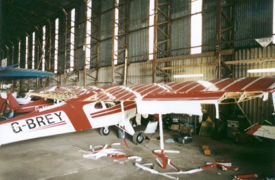
November 2001. The rebuild starts proper. |
 |
Removal of the fabric whilst she
is still in one piece allows photos of general assembly methods, cable routings and some
details to be pictured. This should hopefully assist in the putting-back-together
stage! Inside WWII T2 hangar at EGBG.
[edit: 10 Nov 2003, have a look at the new fuselage paint
scheme] |
 |
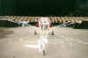 |
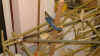
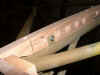
A little more light is required
for some photos, so we drag her out for her last look at blue skies for a while.
Will those rib cap strips support flight?...perhaps only at Mach 1! |
 |
 |
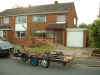
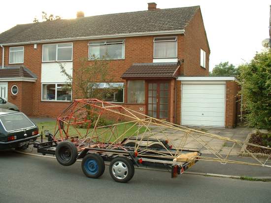
Our group member, John Heard,
bless 'im, provided free transport to my house for the major components. That's me
on the right. Andy Duke on the left. John gets the free advertising in
exchange. |
 |
 |
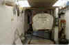
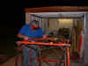
Ensconced in my garage, 8' wide,
32' long; a tight squeeze. Firewall removed from cowl, cleaned up &
Cleco'd back on to renew rivets. 1kW of lighting! |
 |
Fuselage condition OK, no
major corrosion found, but much previous repair work identified, and a few tubes need
straightening. |
November 2001. Fuselage condition,
doors. Click on the thumbnails to enlarge, use the browser's Back button
to go back. |
 |
 |
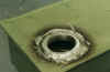
New fairleads
(10 required), use one of the original wire clips to hold it in place.
51/64" outside diameter provides a nice snug fit. |
 |
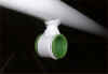 |
.....and
here are the finished articles, November 2002 |
 |
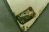 |
The steel door hinges were
attached to the aluminium doors with no paint or other corrosion protection between them,
so dissimilar metal corrosion has occurred, hopefully repairable. |
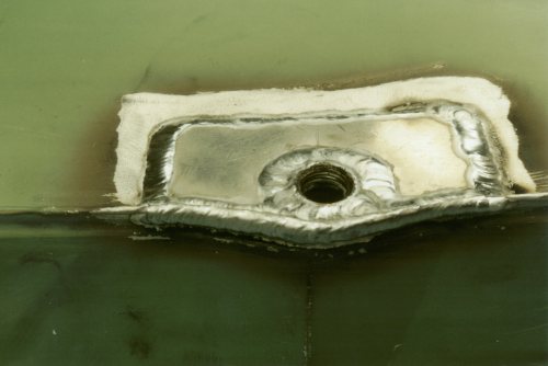
January 2002. Wing fuel
tank. New threaded fittings (for filler neck, outlet and fuel drain) are welded in. |
 |
 |
 |
Reinforcing plates are welded at the same
time to spread the load when connecting up. Filler neck screws in, I didn't like the
glued-in original. |
 |
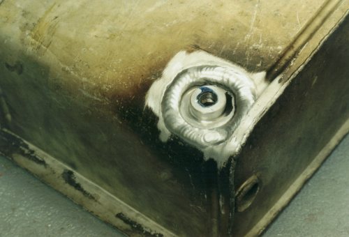
All tanks are leak-tested
after welding in new fittings. Also tests condoms. Pumped up, remained up for
24 hours, only wish I could say the same! One of four tanks leaked at a hairline
crack on one weld, I used gas-fitter's spray to find source of leak. Interestingly,
all the condoms never leaked or burst.
Inflation was through Schraeder valve connected into fuel drain hole. |
|
 |
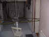
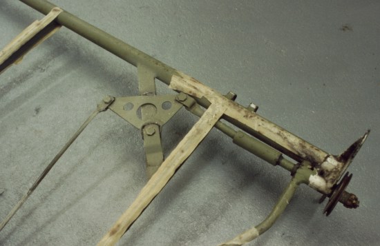
Trim
mechanism, ready for disassembly |
|
|
 |
 |
 |
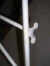
New door hinges are made to weld on to
the steel tube. Previously they were screwed to the wooden frame, but I thought I'd
revert to the better design seen in earlier (pre-1946) models. No "wobble"
or movement on the door now! |
|
|
|
|
April 2002. Woodworking. And more door work. Click on the thumbnails to enlarge, use the browser's Back button
to go back. |
 |
 |
 |
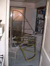
3 views of the new door woodwork going in. I lost
count of the number of times this wood has been on and off, in order to get a better fit
than was there. Wood is American White Ash. |
 |
 |
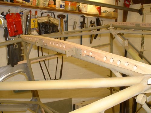
More hours spent on the
skylight woodwork. Lightening holes to reduce the weight of the heavier (and
stronger) ash. |
 |
 |
The doors cleaned up nicely, despite the corrosion seen in earlier
pictures. Note the spot-welded construction.
New interior aluminium panels are made, the old ones were well knackered.
Some reworking of the shape required, especially around the window aperture, using a
shrinker/stretcher.
The hardest part was removing the magnesium door handles! All rivets to be replaced.
|
 |
|
June & July 2002,
largely spent flying in G-BRPX, including a trip to the Le Mans 24-hour race, also flying
in T-Rex to the
Alliance Taylorcraft reunion in Ohio.
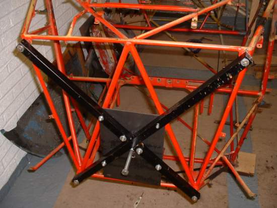
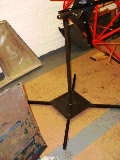
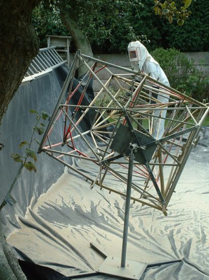
But during this time, I made the fuselage
rotating jig (or at least the front part of it).
 |
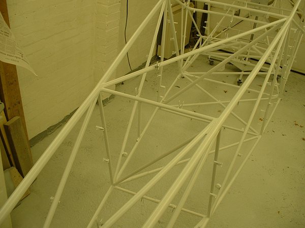
Having finally sorted out the woodwork, and
other bits, I was in the position of being able to turn the fuselage upside down to check
on some things there. |
 |
 |
The jig bolts on to the engine
mounting bolts. |
 |
 |
 |
Because the fuselage needs to tilt as well as
rotate, a swivel is incorporated. A bolt is used to lock the fuselage in the
position required. |
August 2002. Fuselage
work. Click on the thumbnails to
enlarge, use the browser's Back button to go back.
 |
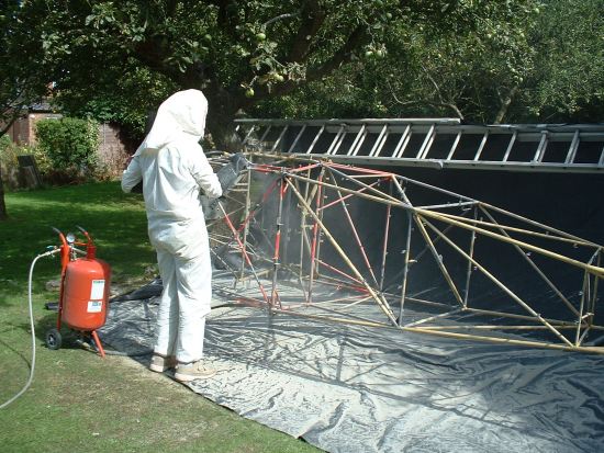
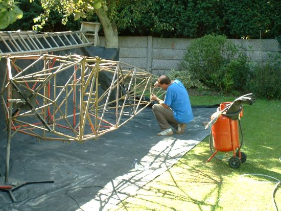
Fuselage leaves my home to go to John Pitts'
house for me to use his beadblasting compressor and for some welding mods. Thanks
for the transport, Eric! |
 |
Welding! |
October 2002
Click on the thumbnails to enlarge, use the browser's Back button to
go back.
 |
 |
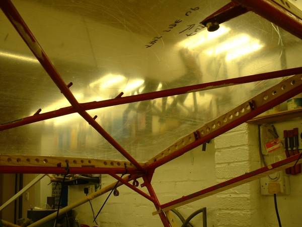
The fuselage made it back home again,
etch-primed. Some trial fitting of the remaining components not already tried,
pending the final coat of two-pack epoxy primer. |
 |
 |
Some straightening of the stabiliser butt rib
achieved using brute force! |
Late October 2002 Click on the thumbnails
to enlarge, use the browser's Back button to go back.
 |
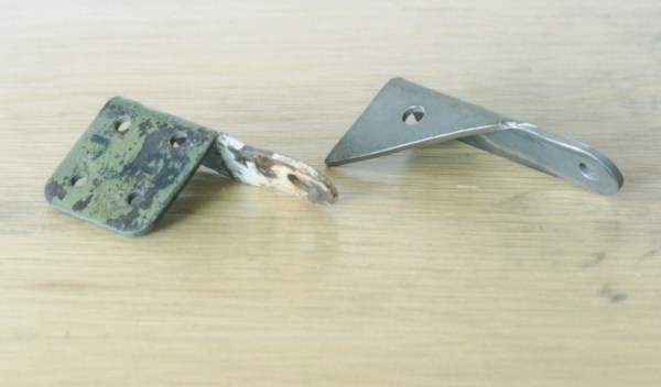
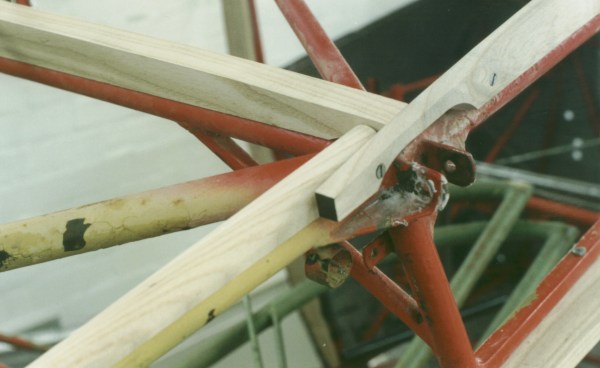
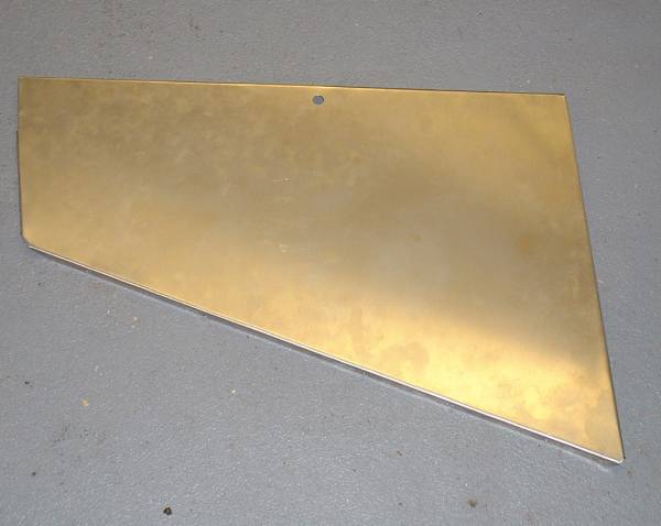
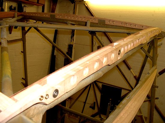
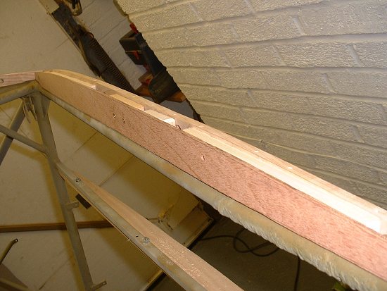
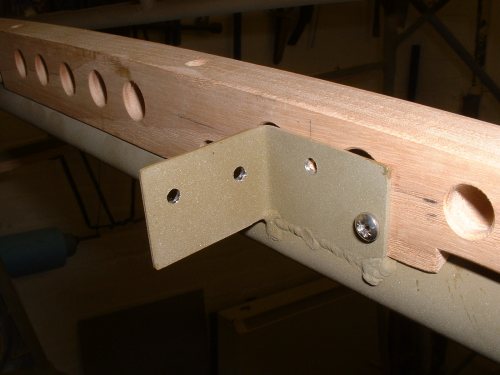
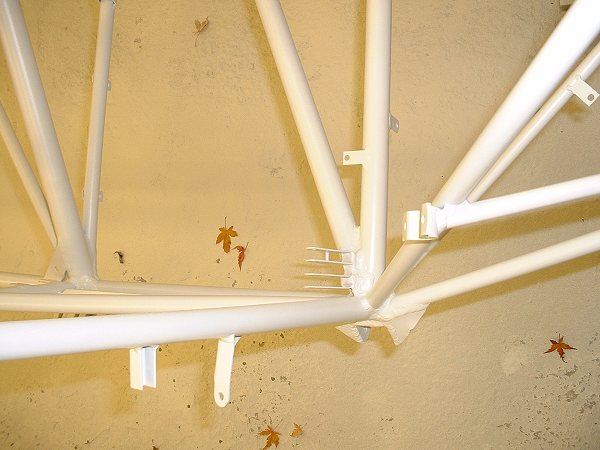
A third view, facing aft, showing one of the additional
new tabs welded forward of the rear spar carry-through tube. This and the L-shaped
bracket above are duplicates of what was on the front spar carry-through tube, and in
total they support the new rear skylight fairing (shown). The block in the bottom
left hand corner is a wooden spacer between the outer former of the wing-root wooden
fairing and the inner plywood (not attached in the photo). |
 |
New hat shelf has a trial fit. Two
pieces, to be reinforced with light stringers to minimise drumming. At the left and
right upper extremities of the back piece are new, welded fittings for the shoulder
harnesses. |
November 2002
Busy month. Click on the
thumbnails to enlarge, use the browser's Back button to go back.
 |
 |
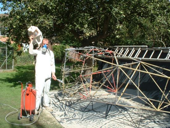
After the gloss coat, all crevices are
injected with waxoil (using a hypodermic syringe) to exclude air & water to eliminate
any corrosion. The excess will be wiped off with white spirit. |
Late November 2002 Click on the thumbnails to enlarge, use the
browser's Back button to go back.
 |
 |
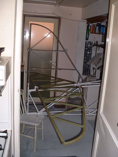
Three views of a trial fit of the
horizontal stabiliser. It encroaches onto the kitchen, and makes a convenient
saucepan holder next to the oven. I will be making a jig to hold the fin and
stabilisers all square for the re-drilling of the stabilise attachment holes in the
fuselage stubs, and later for alignment for the fin covering. |
 |
 |
 |
 |
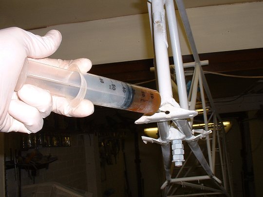
Injecting
linseed oil into the sternpost, using a vetinerary syringe, with the wickedly
sharp point removed. The last picture shows the stuff unexpectedly pouring out of an
aperture at the "H" frame (control column) fitting, to prove that at least some
of the tubes are connected internally. Mopping up on my new white floor required! |
 |
 |
 |
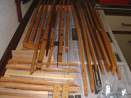
Time now to varnish all my new door frames,
etc. Use a pipe cleaner dunked in varnish to get it down the numerous holes.
Metal mesh holds the paper down; I will later be using this mesh as a screen for small
parts spraying. Recycle! |
 |
 |
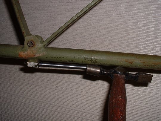
The tail control surface bushings are
driven out using a drift. The same drift will safely insert the new ones. |
 |
Magnesium door handles after bead-blasting
and IMMEDIATELY treated with Stits magna-dyne, this converts the surface to a
grey-coloured inert coating, but must be over-painted within 8 hours. |
 |
Remember that mesh? Spraying small
parts over a mesh stops them blowing away. |
 |
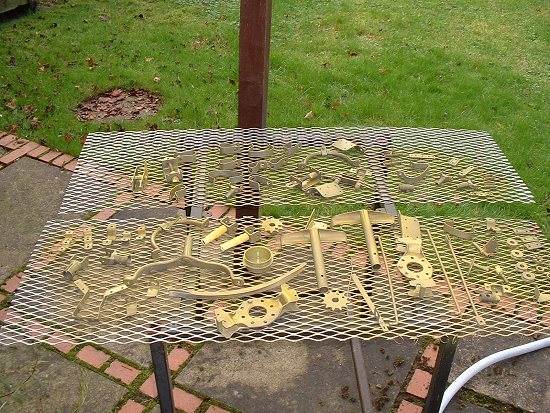
A filthy but necessary job, stripping
parts prior to bead blasting (the bead is too soft to remove this two-pack enamel that the
previous rebuilder used). But take a look
what the H frame looks like after completion! |
|
|
A great achievement, exactly
13 months after BREY was taken off the road, the first components are fitted that won't be
removed again! We are into REASSEMBLY!!! [Go to what it looked like] |
December 2002: Reassembly
continues (and discontinues again) with various works, largely involving a continuation of
the oiling of the internals of the fuselage frame, in response to emails on the
Taylorcraft Email List.
 |
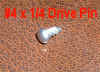 |
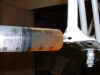
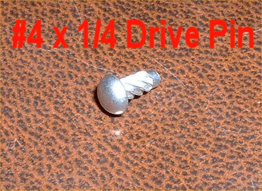
I decide to seal some tubes not otherwise
showing signs of having received previous oiling efforts
The far left photo shows a test of the re-sealing drive pin
inserted in a test piece, to make sure I can re-seal the hole. On the right
here is the finished article. |
 |
 |
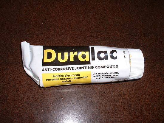
I am using Pigeon Poo (my
colloquial term for "Duralac" barium chromate
paste) to seal the drive pinion. This paste is also very good for sealing rivets,
screws, and any other application where dissimilar metal corrosion may occur, and also
between wood and metal components. I will be using it to protect all my steel bolts
through wood spars, aluminium, etc. Available from Aeronautical or Nautical
suppliers. Excellent stuff. |
|
Also going on is a re-varnish of my
beloved woodwork, after the Randolph one-part varnish decides
to react with the fabric cement after I tested it. So I purchase some 2-part epoxy
varnish from my local boat yard, sand off much of the old stuff, and re-apply in 2-part
epoxy varnish. An industrial sander works well here! I think I'm up to the 150
hour mark on just the new door frames, but they'll be worth it. |
 |
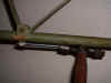
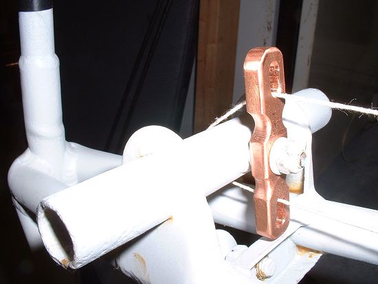
I remanufacture the broken aft trim
cable fairlead, using solid copper. The original was exemplary in its lightness, but
made of fibreboard with copper inserts must have been very expensive to make, but bless CG
for his attention to a light design. But I cannot afford the tooling or time, so I
have ventured for 1/16 oz extra weight and gone for the easy option. I got the
copper from an electrical supplier (it's a standard bus-bar section).
Note: I have still not drilled the welded-up stabiliser holes in the cross-tube... |
 |
 |
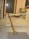
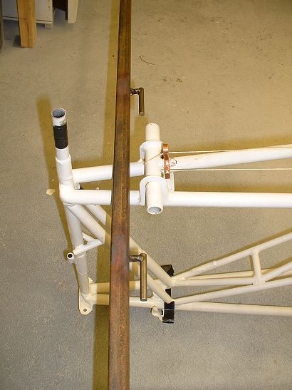
...because I am still working with
my alignment jig. Made from one long piece of random box section, and one long piece
(84") of 5/16 bar welded as one, which is then sawn at the appropriate positions to
fit into the stabiliser hinges. This ensures the 5/16 stubs are in line, good and
true. Photos will follow with it all fitted into the stabilisers and made square
and true with a similar fin/sternpost jig and the tailbrace wires. |
 |
 |
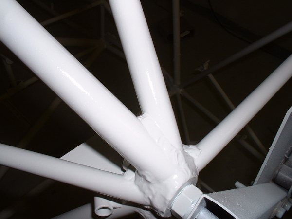
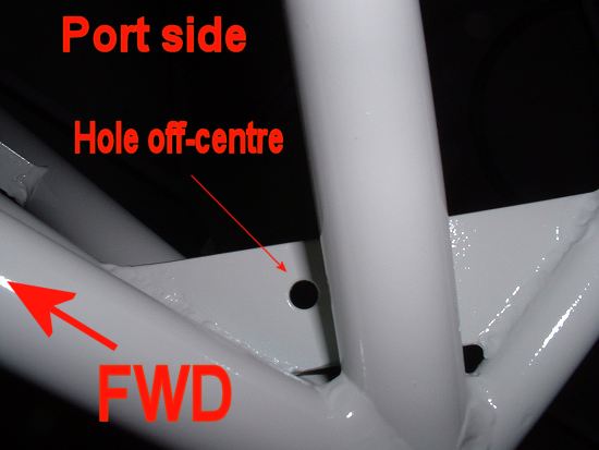
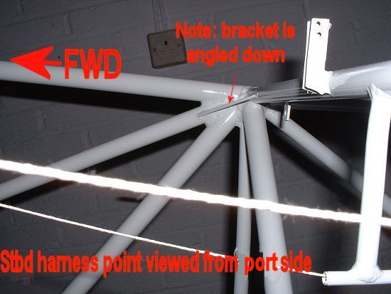
3 views of the shoulder
harness attachment lugs welded into the cluster aft of the headliner. Thank you
Bruce for issuing the details in the Taylorcraft Owner's Club Newsletter. The first
two photos are viewed from vertically above. The third photo is of the starboard
attachment, viewed from the port side. Note the trim cable string lines, no reason, just
there!
The tube marked "FWD" in each case is the upper longeron.
I found that I had to modify the approved Taylorcraft drawing for the port (left)
side because the top diagonal tube got in the way of the hole. The first of these 3
photos shows this. Make cardboard templates first! |
|
 |
 |
Control column shaft bearer is cleaned up.
These were replaced many years ago, and are still serviceable. |
Go to page 1
2 3 4 5 6 7 8
Other
restoration photos
Taylorcraft.org.uk Home


