

Doors, Control Column & Panel
Doors
Control Column
Instrument panel
|
|
The steel door hinges were attached to the aluminium doors with no paint or other corrosion protection between them, so dissimilar metal corrosion has occurred, hopefully repairable. |
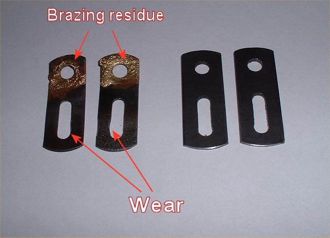 |
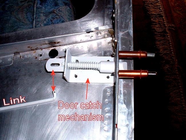
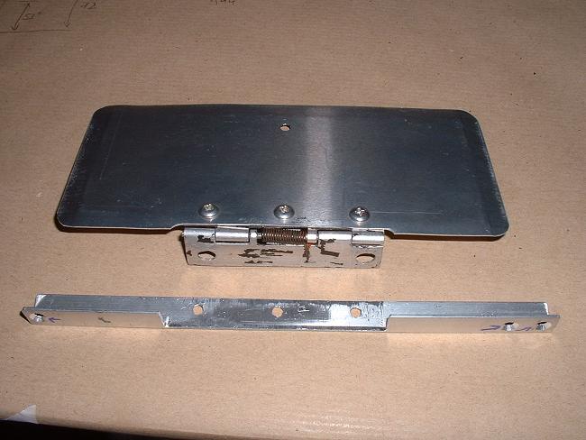
The pic on the left shows two
old and two new door opening tabs. The old ones were worn in the slots, this led to
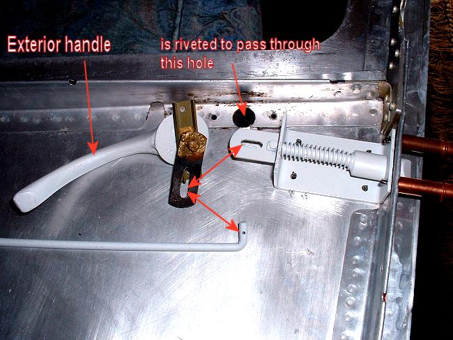
the exterior door handles rattling. The pic on the right shows where these items
fit. These tabs were originally removed by un-brazing them from the handle spindles to facilitate removal of the magnesium handles from the spindles by driving out the pin through the handle. |
 |
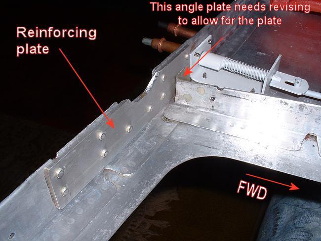 |
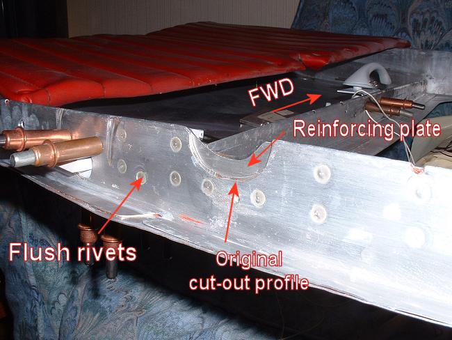
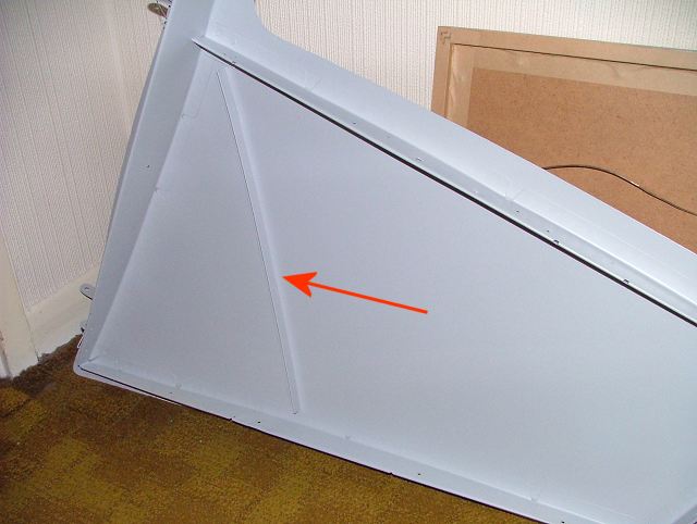
The doors were also
reinforced where there is a semi-circular cut-out for the diagonal tube. There is a
tendency for the doors to flex here, so a good beefy aluminium patch is riveted in to
minimise this. Note how much smaller a cut-out is actually required as compared with
the factory original. Note also the flush rivets used on the outside where the door closes against the frame. However, some modification required to the interior window frame is required to avoid the shop head, and a new right-angle piece is fitted to allow for the locally increased thickness. Note the epoxy primed door handle in the right-hand photo, this was primed very soon after magna-dyning. |
 |
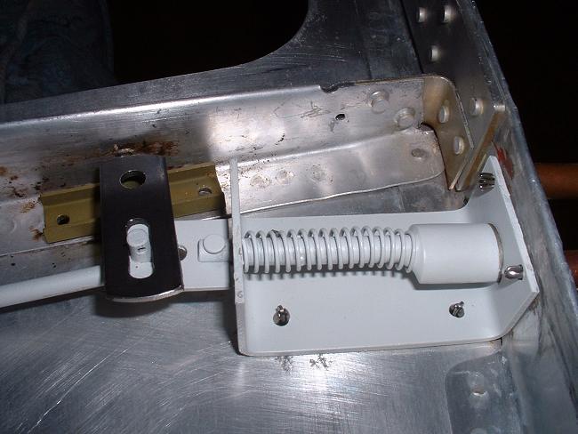
Door mechanism photos:
 |
 |
 |
 |
 |
I am going to have my interior handle pointing forward to keep out of the occupants' way. |
 |
Magnesium door handles after bead-blasting and IMMEDIATELY treated with Stits magna-dyne, this converts the surface to a grey-coloured inert coating, but must be over-painted within 8 hours. |
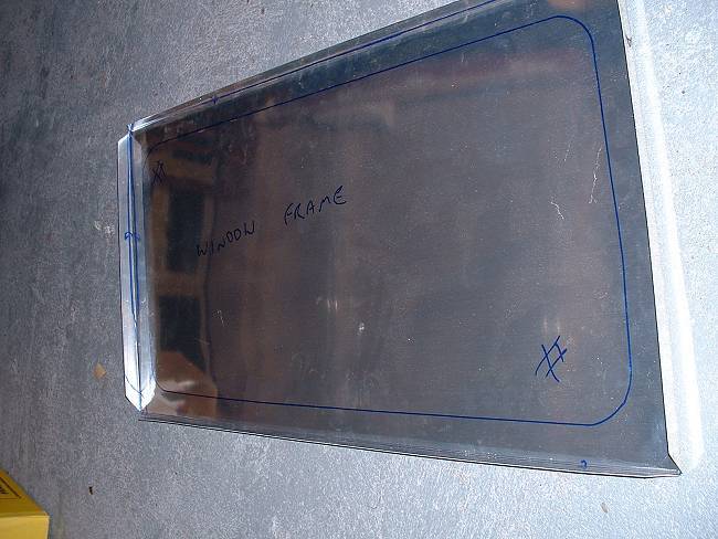 |
Making new interior window
frame for one of the metal doors. 0.025" 2024T3 material used. I used the original frame to mark the new one out, it would be difficult to make without. |
 |
Here, I have added a stringer to the inside of the outer door skins, to reduce the pushing in of the bowed skin... |  |
...I do the same to the new inner door panels, but this is to prevent drumming of the flat panel. |
 |
I also paint the white on the doors first, then mask off for red... | 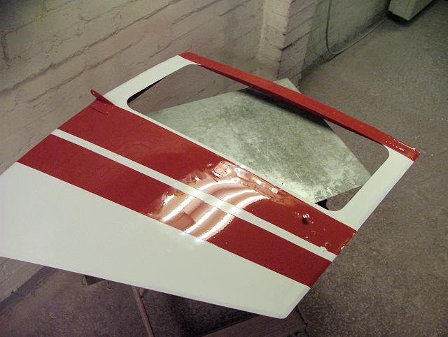 |
...and again I am now pleased with the final effect. |
 |
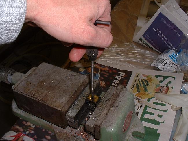
A filthy but necessary job, stripping parts prior to bead blasting (the bead is too soft to remove this two-pack enamel that the previous rebuilder used). |
 |
 |
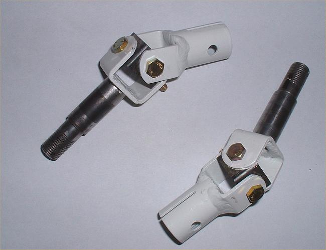
Further control system work also continues on the universal joint [UJ] of the control column. Much of the "slop" in the aileron system was caused by very elongated holes in the central part of the UJ system, much too much to "punch and re-ream" so I welded up the out-of-round holes and redrilled them. It is important to note that each pair of opposing 3/16" diameter holes are displaced from each other, this gives clearance between the AN3 bolts that are at 90 degrees inside this assembly! This far left pic shows a "before and after" pair. The section is 3/4" internal seamless square. The adjacent pic shows the 3/16" taper reamer. |
 |
 |
And here they are installed (albeit temporarily, without the correct castellated nuts & split pins). But no slop! The spindles have a spiral groove machines into them to assist with distribution of lubricating oil. CG knew his stuff! There is an oiling hole right on top of the H frame arms. As the "H" frame swings fore-and-aft, it distributes the pool of oil towards these helix grooves. |
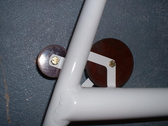 |
I also had some trouble with the pulleys fitted
to the control "H" frame...they had a tendency to rub against the sides of the
frames that they are bolted to. I didn't know this until I tried to reassemble. This
had evidently been the case for a long time (and perhaps since new) because in order to
rectify the situation, I needed to straighten these frames that hold both the small and
large diameter pulleys. I would suggest that anyone doing a restoration should check
this before final painting! Fortunately, I was able to get all the pulleys to free-run without damaging the paintwork too much, with the judicious use of a hammer and some washers. I would now challenge anyone to have free-er running pulleys than me! (and mine are bushed, none of this ball-bearing stuff!) |
 |
 |
We wanted a transponder in the right hand
glove-box for touring in Europe, where many countries now make transponder mandatory. The
transponder was installed in 2001 for a tour of Germany and Austria. So a new, smaller glove-box door is made, with an angle-piece to support it. I will be making a new shallower glovebox in which we can put a chart, spare batteries, toothbrush, condoms etc, and other essential touring supplies. |
| You may note in the
right hand photo above, a small rectangular hole to the left of the transponder... this
was put in some years ago so that we could withdraw the rod that goes through the fuselage
fuel tank. This small rectangular hole means that the whole panel does not need to
be removed to drop the tank. The hole will be covered by a plate with the "fuel transfer" label attached to it. |
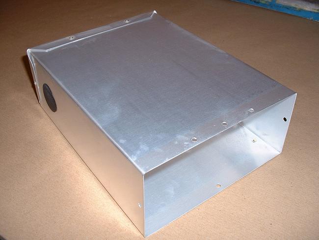 |
New shallow glove box for the space above the
transponder. Before riveting up, the aluminium has been acid-etched and treated
using Poly-Fiber "Aluma-Dyne", which leaves no colour. Blanked-off hole is for any future electrical / power supply access in case we put a gadget inside the box. Anyone designing a hand-held / portable transponder? |
 |
I make a new left-hand glove box. In this we install two gel-cell batteries, an intercom, PTT connections, GPS power supply and all necessary fuses. One battery will operate the Icom hand-held radio, the other one powers the GPS. If the radio battery gets low, a throw-over switch changes the radio source to the GPS battery and vice-versa. The GPS is quite happy to continue to draw power from the battery that the radio was draining, because the GPS has a lower power requirement. |
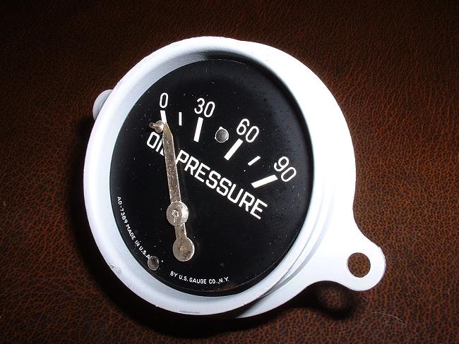 |
The instruments are given the once-over...in this case the oil pressure gauge has been stripped and the corroded case cleaned up and epoxy-primed before reassembly. I still need to repaint the needle, and I will be marking the limits on the gauge face instead of on the glass as was previously the case... |
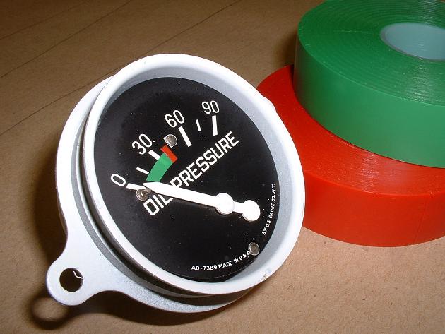 |
...and here it is marked up with the limits and a painted needle. I used regular electrician's insulating tape for the markings, referencing the type cert and Service Manual to ensure I put the correct limits in. |
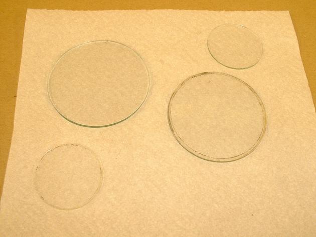 |
The instrument glass faces getting prepared for a clean up. |
Fuselage structural work
Fuselage Fabric
Wing Structural work
Wing Fabric
Ailerons
Cowls
Tailfeathers & Gear Legs
Doors Control Column & Panel
Final Assembly